- Drill + Cutting Machine Using 775 DC Motor and PVC Pipe

This project involves designing a DIY drill and cutting machine using a 775 DC motor, 2-inch PVC pipe with end caps, and essential electrical components. This compact and versatile tool can be used for both drilling and cutting operations, making it a great addition to any DIY workspace.
How the System Works

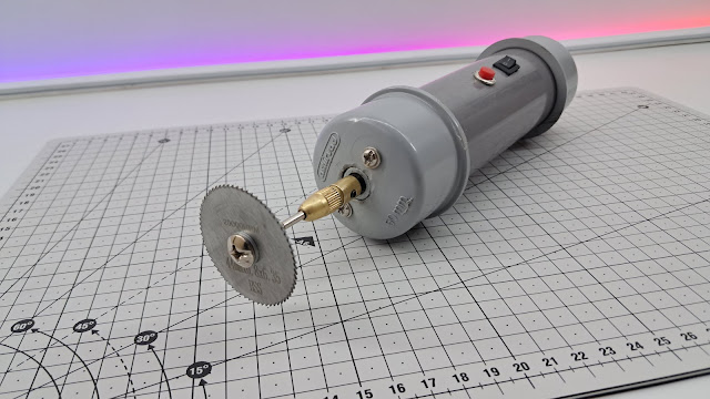
The system utilizes a 775 DC motor mounted inside a 2-inch PVC pipe, with a drill chuck attached to the motor shaft. A small switch and push button control the motor’s operation. Power is supplied using a 24V power source, and interchangeable tool heads allow switching between drilling and cutting functions.
Components List
775 DC Motor (High torque, 12V-24V)
2-inch PVC Pipe (Body structure)
PVC End Caps (Securing motor inside pipe)
Chuck (To hold drill bits and saw blade)
Drill Bits (For drilling operations)
Cutting Saw Blade (For cutting applications)
Small Switch (ON/OFF control)
Push Button (Momentary operation)
Wires (Electrical connections)
24V Power Supply (To power the motor)
Male Connector and Female Socket DC (For secure power connections)
Material Required
775 DC motor :- Buy Here
Small Switch :- Buy Here
Push Button :- Buy Here
Wires :- Buy Here
Drill Chuck :- Buy Here
Drill Chuck 2 :- Buy Here
Drill Bits :- Buy Here
Cutting Blades :- Buy Here
Socket and Connector :- Buy Here
Power Supply :- Buy Here
Assembly & Construction
Mount the 775 DC Motor:
Drill a hole in one PVC end cap for the motor shaft.
Insert the motor inside the PVC pipe and secure it with screws or epoxy.
Ensure the shaft extends out of the pipe for tool attachment.
Attach the Chuck & Cutting Saw:
Connect the drill chuck to the motor shaft securely.
Use drill bits for drilling operations.
Swap drill bits with a small saw blade for cutting functionality.
Electrical Wiring Setup:
Connect the small switch for ON/OFF control.
Add a push button for momentary operation.
Properly route and insulate wires inside the PVC pipe.
Power Connection (24V Supply):
Connect the motor to a 24V power source.
Use a DC jack or direct terminals for easy connectivity.
Circuit Diagram

This circuit consists of:
A 775 DC motor connected to a 24V power supply
A small switch for ON/OFF control
A push button for momentary operation
Male connector and female socket DC for secure power connections
Proper wiring connections to ensure safety and functionality
Why Choose This Design?
Compact & Lightweight: Uses PVC pipe for easy handling.
Multi-Functional: Supports both drilling and cutting.
Easy Assembly: Simple wiring and mechanical setup.
Budget-Friendly: Uses readily available materials.
Key Benefits
This DIY drill and cutting machine is an excellent project for electronics enthusiasts and DIY makers. It provides hands-on experience with DC motors, electrical wiring, and tool-making, making it a great learning opportunity while building a practical tool.
Comments
Post a Comment